3.2.1. Create OcTree Mesh Input File
The OcTree mesh used in the TDoctree code are created using the program create_octree_mesh_td.exe. Parameters necessary for defining the OcTree mesh are set in the input file. The lines within the input file are as follows:
Line # |
Parameter |
Descriptions |
|---|---|---|
1 |
min. cell widths in x, y and z for base mesh |
|
2 |
sets the total mesh extent in x, y, down and up directions |
|
3 |
sets cell sizes within core mesh region |
|
4 |
sets thickness of cells of finest discretization near receivers |
|
5 |
the file containing transmitters and observation locations |
|
6 |
sets topography |
|
7 |
Sets lateral extent of core region |
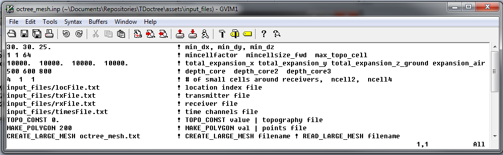
Fig. 3.1 Example input file for creating octree mesh (Download )
3.2.1.1. Line Descriptions
dx dy dz: Minimum cell widths in x, y and z for the base mesh.
x_pad y_pad down_pad up_pad: Distance from the survey area in the x, y, downward and upward directions, respectively, that the mesh extends.
h1 h2 h3: Sets cell sizes within the core mesh region. Up to a depth of h1 from surface topography, the smallest cell size is used (set by dx, dy, dz). For the following h2 metres, the cell widths are doubled. For the following h3 metres, the cell widths are doubled again. Outside a depth and horizontal distance of h1+h2+h3, the cells widths increase by a factor of 2 for every additional layer (see the figure below).
n1 n2 n3: This sets the thicknesses of layers of finest discretization near the receivers. n1 = 4 means that around each receiver, there is a layer 4 cells thick that uses the finest discretization. This is followed by a layer which is n2 cells thick, where the cell dimensions are increased by a factor of 2. Likewise for the 3rd layer.
locFile: Contains the locations of the receivers. The user may either enter the file path to an observed data file, or the flag “ONLY_LOC” followed by the path to a data points file.
topoFile: If a topography file is available, the file path to the topography file is entered; see topography file for format. In the case of flat topography, the user instead enter “TOPO_CONST”, followed by a space, then the elevation of the surface topography; for example “TOPO_CONST 125.5”.
polygon options: This sets the lateral extent of the core mesh region. Here, there are two options
The flag MAKE_POLYGON is entered followed by a positive value (val). Up to a lateral distance val from all transmitters, the finest mesh discretization is used.
Enter the file path to a polygon file. The polygon denotes the points of a convex hull that is used to define the lateral extent of the core mesh region.