3.3.1. Survey and Locations File
The survey and locations file is used to predict synthetic field data (forward modeling). This file contains all necessary survey information including: the number of transmitters, transmitter geometry, observation locations and frequencies.
Note
Bolded entries are fixed flags recognized by the Fortran codes and blue hyperlinked entries are values/regular expressions specified by the user
The lines of the survey file are formatted as follows:
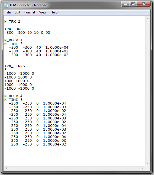
Fig. 3.5 Example survey file with various types of transmitters.
3.3.1.1. Parameter Descriptions
n_trx: The total number of unique transmitters. Example: N_TRX 3
n_recv: The number of receivers collecting field observations for a particular transmitter.
n_time: The number of time channels for each receiver
3.3.1.2. Defining Transmitters
There are two types of transmitters that TDoctree survey files can use
3.3.1.2.1. Circular loop transmitter
This is an inductive source. The circular loop transmitter is defined using two lines:
where
TRX_LOOP is a flag that must be entered
\(x\) is the Easting, \(y\) is the Northing and \(z\) is the elevation location of the center of the loop
\(R\) is the radius of the loop
\(\theta\) is the azimuthal angle in degrees. A horizontal loop is defined by \(\theta = 0\)
\(\alpha\) is the clockwise angle from northing in degrees
3.3.1.2.2. Large inductive source
Here, we define the inductive source using a set of wire segments. When defining this type of transmitter, you must close the loop. The block defining this transmitter is given by:
where
TRX_LINES is a flag that must be entered
\(N\) is the number of nodes (# segments - 1)
\(x_i, \; y_i \; z_i\) are Easting, Northing and elevation locations for the nodes