3.3.5. Transmitter and Receiver Files
The exact dimensions of the transmitters or receivers used to model FEM data are defined within a transmitter or a receiver file, respectively; i.e. transmitters are defined within a transmitter file and receivers are defined within a receivers file. Because transmitters and receivers are both defined as wire segments, the format of the transmitter and receiver files is identical.
Note
Bolded entries are fixed flags recognized by the Fortran codes and blue hyperlinked entries are values/regular expressions specified by the user
3.3.5.1. Format
The lines of a transmitter/receiver file are formatted as follows:
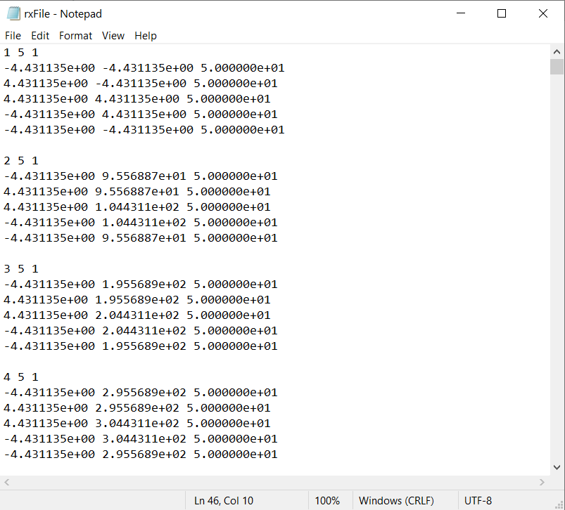
Below is an example of a transmitters or receivers file where the respective items are closed horizontal loops.
3.3.5.2. Parameter Descriptions
ID: A unique index number for the transmitter or receiver. The index numbers should be increasing.
N: The number of points defining the transmitter/receiver.
1: As of May 2018, a flag value of 1 is entered here. In future iterations of the code, this entry may be related to additional functionality.
\(\mathbf{x_i \;\; y_i \;\; z_i}\): Denotes the X (Easting), Y (Northing) and Z (elevation) locations for nodes defining transmitter/receiver.
Loop transmitter/receiver: When defining a loop transmitter or receiver, you must close the loop; e.g. the fist and last nodes must be at the same locations. The transmitters and receivers are defined in a left-handed (clockwise) manner. For example, a horizontal loop must be defined in a clockwise manner for its dipole moment to be in the vertical direction.
Wire transmitter/receiver: If the first and last nodes are not in the same place, the user will define a grounded receiver which measures the electric field. The grounded loop can be more than one segment long.
3.3.5.3. Comments on Data Units
Electric Field Data (e): For electric field measurements, the code intergrates the electric field of the path of the wire then divides by its length. Thus electric field data are the average electric field measured over the path of the wire in units V/m.
Time-Derivative of Magnetic Flux Data (db/dt): For dB/dt measurements, the code integrates the electric field over the path of the wire, multiplies by -1 (giving the EMF), then normalizes by the area of the loop. The data are therefore the average value of dB/dt in the direction of the loop’s moment. The units for dB/dt measurements are T/s.
Magnetic Field Data (h): Similar to the time-derivative, H-field measurements represent the average value H in the direction of the loop’s moment. H-field measurements are in units of A/m.